Introduction
Get the column–beam joint wrong and the whole structure pays for it. A precast column cap is the compact hub where beams, walls, and columns meet, making or breaking load paths, construction timelines, and long-term durability. In projects utilized across bridges and buildings, precast concrete columns with column caps deliver many benefits: speed, quality, and an extended service life when the engineering is done right.
Why the precast column cap matters
A prefabricated concrete columns cap is the support node that spreads concentrated actions from precast beams and slabs into the concrete column, ensuring gravity and lateral loads reach the foundation without detours or hot-spots; it also accepts architectural finishes so the joint can be both tough and refined.
In structural engineering service work, the cap is where prefabricated concrete columns interface with diaphragms and steel embeds, so its stiffness, shape, and detailing govern how the frame stands under service loads and how it yields under extreme events.
Load paths and lateral systems
For buildings, choose and design the lateral system first – shear walls, moment frames, or hybrid – and size the prefabricated concrete columns cap for the actual force path: vertical bearing + horizontal shear + torsion transferred into precast columns and diaphragms. Caltrans guidance frames bent caps as the member that passes superstructure loads to the columns and then the ground under wind and earthquake actions.
In precast concrete frames, diaphragms formed by hollow-core or double-tee systems must tie into the cap with reinforcement or topping so that in-plane shear reaches the vertical structural components.
Connection engineering that controls performance
A cap’s value is defined by its connections. The most common options and where they fit are below (pick based on load, ductility, and installation constraints):
| Connection | Where it shines | Key engineering notes |
|---|---|---|
| Grouted vertical ducts | Bridges/buildings needing fast field assembly | Proven with TxDOT; capacity hinges on duct diameter, embedment, grout properties, and bar development. |
| Grouted splice sleeves | ABC in seismic regions | PCI studies show column-to-cap sleeve joints can meet strength/ductility for moderate–high seismic use when sleeves stay out of plastic hinges. |
| Pocket (socket) connections | Tolerance-friendly caps, good continuity | Pocket depth, confinement, and consolidation quality control the moment and shear transfer. |
| Bolted/welded steel hardware | Dry, rapid erection; retrofit | Excellent for pure shear; for moment take care with plate thickness, edge distances, and fire protection of steel. |
➡️ Practical takeaway: design the prefabricated concrete columns cap to remain essentially elastic while the adjoining concrete column provides ductility—then select the connection that delivers that behavior, not the other way around.
Materials, durability, and fire resistance
Concrete: factory mixes for caps typically use high strength and low water–cement ratio, often with SCMs for durability; SCC helps consolidate congestion around ducts/sleeves.
Freeze–thaw: DOT practice targets ~5–7% total air for freeze–thaw–exposed building materials; FHWA also aligns air content and w/cm limits with exposure class.
Evidence base: properly air-entrained concretes (≥ ~6% fresh air in many studies) sustain high durability factors through hundreds of cycles.
Fire resistance: achieve ratings with cover, member thickness, and aggregate choice; protect any steel plates or bolts (encasement or coatings) because hot steel can lose capacity before the concrete does.
Manufacturing tolerances and installation
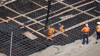
Manufacturing: plant QA controls batching, curing, and embedded locations so caps fit virtually “plug-and-play” on site; typical dimensional tolerances are in the ±¼–½ in range for cross-section and length to ensure proper bearing and splice fit.
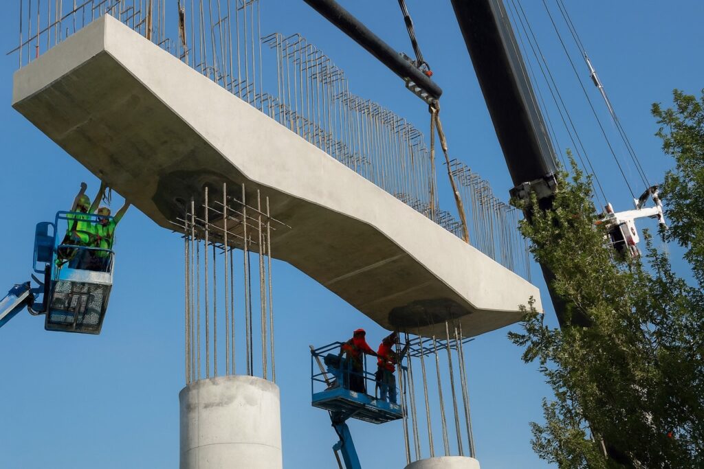
Interface geometry: in bridges and long-span frames, consider large block-outs or recesses to absorb column and cap tolerances; ensure bearing pads or collars keep elevations co-planar so rigid elements do not “three-point” and shed load unintentionally.
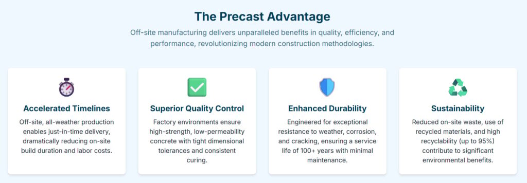
Construction timelines: off-site manufacturing of caps can compress critical closures, a visible benefit for builders and road users.
Seismic design and capacity protection
Capacity protection: keep the prefabricated concrete columns cap elastic while allowing plastic hinging in the column; detail confinement and development so the joint can pass peak shear and moment without brittle failure.
Sleeve joints: PCI research shows column-to-cap sleeve joints can achieve strength, displacement ductility, and reparability targets for ABC when sleeves are located away from plastic hinges and detailing follows tested envelopes.
Current criteria: recent Caltrans Seismic Design Criteria (2025) cite research on precast girder-to-cap and cap connections for integral bridges—use the latest provisions when caps participate in lateral resistance.
Proven results from real projects
- US-290 Ramp G (Houston): cast-in-place bent-cap work would have closed a ramp ~41 days; switching to a precast cap cut the closure to 6 hours—a striking example of accelerated installation.
- Pierce Elevated (Houston): replacement of 113 spans using precast bent caps reduced a >1.5-year job to 95 days, demonstrating schedule and user-cost savings that a capable structural engineering service can quantify in bids.
- System development: PCI studies catalog grouted ducts, pockets, sleeves, bolted variants and their anchorage behaviors – the tested menu a project team should draw from, not reinvent.
Design assistance checklist
Validate the load path: trace gravity, shear, and torsion from beams and diaphragms through the precast column cap into precast columns and the foundation; confirm diaphragm collectors and edge reinforcement actually reach the cap seats.
Select the connection by demanded rotations and repair strategy: wet (ducts/sleeves/pockets) for continuity and seismic rotations; dry (bolts/plates) where speed and access rule; hybrid for staged industrial applications.
Specify materials for environment: air content per exposure class, low w/cm, SCMs, and cover for chloride or de-icing loads; document test methods (ASTM C231/C173) in the cap schedule.
Lock in tolerances early: show seat elevations, pocket depths, and sleeve locations in the BIM/shops; mandate plant QA and field checklists that protect bar development, grout quality, and bearing area.
Address fire resistance now: assign cover and any steel protection to preserve capacity under heating; coordinate with building fire ratings and additional information from local codes.
Plan for design assistance and procurement: engage the structural engineering service at concept so precast concrete suppliers can optimize forms for repeated use, reducing cost for last generations of similar assets while keeping options open for shape refinements.
Conclusion
A precast column cap is small in volume yet decisive in performance. Treat it as a designed node – not a block – by aligning the lateral system, selecting the right connection, specifying durable concrete, and enforcing tolerances. Do that, and precast concrete columns and caps deliver the many benefits promised by precast concrete: reliable installation, shorter construction timelines, robust fire resistance, and an extended service life across bridge and building work.
If you are planning projects with precast concrete columns and caps, explore how BuildTwin can support your structural engineering service with real-time digital insights, tolerance tracking, and lifecycle monitoring. Build smarter, faster, and safer with data that stands by your structure.