1. Introduction
Concrete building footings, or concrete footing assemblies, are the load-spreading elements that anchor a structure’s foundation to the ground, converting building loads into safe soil pressures. Designed to spread the weight evenly and prevent settlement, cracking, or moisture intrusion, concrete footings are the first and most critical step in residential footing construction. From single-pad isolated footings under columns to full-slab raft systems, understanding concrete footing detail and what is concrete footing is key for builders committed to safe, durable homes.
2. Understanding Concrete Footings
This section covers concrete footing types, concrete footing detail, and answers what is concrete footing with clarity.
2.1 What Is Concrete Footing?
A concrete footing is one of the concrete footing types that serves as the widened base of a structure’s foundation, poured into excavated trenches to spread loads over a larger soil area and prevent excessive settlement. It sits directly under foundation walls or columns, transferring vertical and lateral forces into the soil and acting as a barrier against moisture migration. Properly executed concrete footings ensure uniform bearing pressure, minimizing the risk of differential settlement that can cause structural distress.
2.2 Footing vs Foundation
While the concrete footing is the component in contact with the soil, the foundation includes all structural elements that transfer building loads from the superstructure to the ground. Think of concrete footings as the “feet” of a building and foundation walls or slabs as the “legs” that rise above grade to support load-bearing elements. Footings spread the weight at the soil interface; foundations include walls, slabs, and other elements bridging between the footing and the above-ground structure.
All concrete footing types are shallow foundations, but not all foundations are footings—deep elements like pile footings or caissons also qualify as foundations.
2.3 Why Concrete Dominates Footing Construction
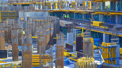
Concrete’s high compressive strength, durability, and versatility make it the material of choice for concrete footing construction. Factory-tested concrete mixes achieve compressive strengths of over 2,500 psi, ensuring consistent performance under sustained loads and moisture exposure. Fresh concrete’s plasticity allows footings to conform to complex trench geometries, while compatibility with steel reinforcement (rebar in foundation footings) provides the tensile capacity to resist bending and soil-induced stresses. The material’s inherent fire resistance, low maintenance, and cost-effectiveness solidify its dominance in foundation footings worldwide.
3. The Role of Rebar in Foundation Footings
3.1 Concrete’s Weakness, Steel’s Strength: The Role of Rebar for Tensile Forces
Plain concrete footings excel in compression but lack tensile capacity. Embedding rebar in foundation footings compensates by providing high tensile strength where the footing experiences bending moments. This composite action increases ductility, allowing footings to deform under load without sudden failure and distribute stresses more evenly across the concrete footing section.
3.2 Types of Rebar
Rebar comes in various grades per ASTM to ensure predictable yield strengths in footing construction.
Common grades for concrete footings are Grade 40 (40,000 psi) and Grade 60 (60,000 psi); heavy-load applications may use Grade 75 or 100.
Steel types include carbon steel (ASTM A615/A615M), low-alloy steel (ASTM A706/A706M), and stainless variants—selected based on strength, ductility, and corrosion resistance. Bar sizes range from #4 (½ in.) to #8 (1 in.), determined by design loads, concrete footing detail, and code requirements.
3.3 Best Practices for Rebar Placement: Ensuring Optimal Structural Integrity
Lay rebar in a grid (8–12 in O.C.) with minimum 3 in cover to soil-facing surfaces, using chairs to prevent “floating” during pouring.
Use lap splices or mechanical couplers to achieve development length, ensuring continuity through hooks and ties.
Inspect bar alignment and spacing before placing concrete footing to guarantee designed load distribution and crack control.

4. Calculating Concrete Footings – Key Factors and Methods
When calculating concrete footings, engineers balance soil capacity, structural demands, environmental constraints, and code requirements to determine safe and serviceable footing dimensions. This section demystifies calculating concrete footings with critical inputs and proven methods.
The process starts with determining the soil’s allowable bearing capacity – derived from ultimate capacity tests and reduced by safety factors – and calculating factored loads from dead, live, wind and seismic forces. Regional frost depths dictate minimum embedment to prevent heave, while soil classification (clay, silt, sand, gravel) drives adjustments for settlement and drainage. With these inputs, designers apply the fundamental sizing formula (A = P/q_allow), calculate concrete volumes, allocate loads via tributary areas and where applicable use prescriptive code tables to simplify sizing for common residential scenarios.
4.1 Identifying the Critical Inputs: Factors Influencing Footing Design
At the heart of footing design is the soil’s allowable bearing capacity, defined as the maximum pressure the soil can support without shear failure or exceeding settlement limits. Engineers derive the allowable bearing capacity (q_allow) by dividing the net ultimate bearing capacity (q_u) by a safety factor – typically between 2.5 and 3.0 – thus incorporating both strength and settlement considerations. The net ultimate bearing capacity itself accounts for the soil’s cohesion (cʹ), unit weight (γ), footing depth (D) and width (B) through Terzaghi’s classic expression:
qu=cʹNc+γD Nq+0.5 γB Nγ,
where Nc, Nq and Nγ are bearing capacity factors determined by the soil’s angle of internal friction.
Footings must support combined dead, live, wind and seismic loads according to code prescribed load combinations, ensuring factored bearing pressures are within soil capacity. Load magnitudes are calculated by summing permanent (dead) loads – self weight of footing and structure – and variable (live) loads, then applying load factors from ACI 318 or IBC (e.g. 1.2D + 1.6L for ultimate strength design) to determine factored design loads. Prescriptive tables in the IRC (Table R401.4.1) and IBC (Section 1809.7) provide minimum footing sizes for tributary loads and soil pressures for light-frame construction, for common residential scenarios. For example the IRC requires a minimum footing width of 12 in for one- and two-story buildings on undisturbed soil with at least 2,500 psi concrete.
To prevent frost heave, footings must extend below the regional frost line, which varies from 12 in in southern states to over 60 in in northern jurisdictions; for example Minnesota requires a minimum depth of 48 in per frost depth maps.
Soil classification – clay, silt, sand or gravel – affects bearing capacity, consolidation behavior, drainage characteristics, and the load bearing value. clays may have lower bearing capacities (1,500–3,000 psf) and delayed consolidation, while sandy gravels can exceed 6,000 psf. Soil specific tests such as the Standard Penetration Test (SPT) or Plate Load Test inform q_allow and guide adjustments to footing width, depth and compaction requirements.
4.2 Methods for Determining Footing Dimensions
The fundamental sizing equation for isolated footings is
A = P ÷ qallow
where P is the total factored column load and qallow is the allowable soil bearing capacity; for net allowable capacity, the self weight of soil above the footing base is subtracted before division.
Once footing area (A) and depth are determined, concrete volume is calculated as
Volume = Length × Width × Depth,
yielding cubic feet, then converted to cubic yards by dividing by 27 (e.g. a 4 ft × 4 ft × 1 ft footing requires 16 ft³ or 0.59 cubic yd).
In strip and combined footings the tributary area concept distributes building loads to each footing segment by dividing the floor or wall length by the number of supporting elements; tributary widths guide strip footing sizing per IRC Table R401.4.1, where footing width = (tributary load length × tributary width)/q_allow .For expediency in light-frame residential construction, builders often use prescriptive tables (e.g. IRC R401.4.1 and IBC 1809.7) that correlate soil pressures (1,500–3,000 psf) and tributary loads to minimum footing dimensions, eliminating detailed calculations for spans under 16 ft.
5. Types of Footings
Footing selection in foundation construction and concrete footing construction depends on site conditions, load demands, and soil characteristics. We cover the main concrete footing types—shallow and deep—to guide your design and illustrate concrete footing detail and concrete footing types.
5.A Shallow Footings
Shallow footings are used when stable bearing strata is near the surface, providing cost-effective support for light to moderate loads in residential construction and concrete footing construction.
5.A.1 Isolated (Pad) Footings
Isolated footings – also called pad or spread footings – are individual concrete pads under single columns, pilasters or point loads to spread concentrated forces over a wider soil area. They can be reinforced when support demands are higher or non-reinforced with increased depth for lower loads; the choice depends on structural loads and soil bearing capacity. Typical applications include residential columns, light-frame construction and pier supports where loads are discrete rather than continuous.
5.A.2 Strip (Continuous) Footings
Strip footings are a continuous concrete strip under load bearing walls or closely spaced columns, transferring linear wall loads into the ground . Width is determined by dividing the wall’s tributary load by allowable soil pressure, with common practice doubling wall thickness for adequate spread. Variations include stepped strip footings on sloped grades and reinforced strips in seismic zones, to ensure uniform bearing and minimize differential settlement.
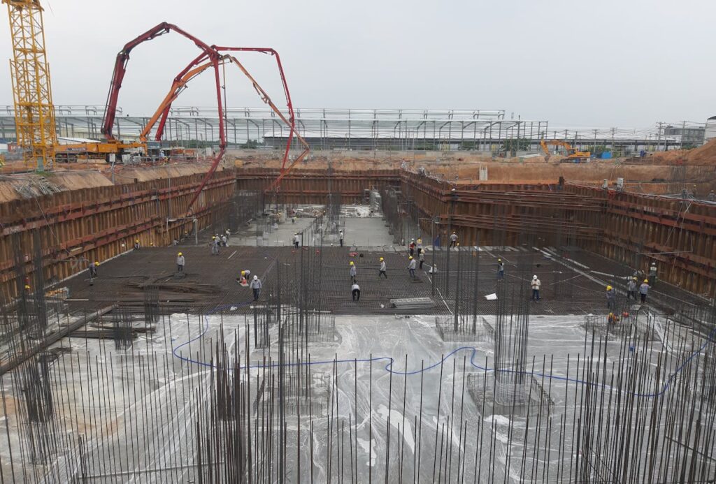
5.A.3 Raft (Mat) Foundations
A raft or mat foundation is a large, thick concrete slab spanning the entire building footprint to distribute superstructure loads across poor or variable soils. Reinforced with a steel grid, mats counteract differential settlement by acting as a single structural element, ideal for commercial buildings, light industrial facilities, and crawl spaces in areas with low soil bearing capacity below 3,000 psf. Mat foundations also serve as combined footing systems when column spacing is dense, unifying loads into one slab.
5.A.4 Combined Footings
Combined footings support two or more columns when isolated footings would overlap or when columns are near property lines, balancing eccentric loads through shapes like rectangular or trapezoidal slabs. In trapezoidal combined footings, the wider end under the heavier column shifts the centroid to align with resultant loads, preventing overturning. Strap combined footings use a connecting beam (strap) between isolated pads to transfer moments without increasing soil pressure directly under one pad.
5.A.5 Stepped Footings
Stepped footings adapt to sloping terrain by “stepping” down in discrete levels, maintaining consistent embedment depth while following ground contours. This approach reduces costly cut-and-fill operations and preserves natural drainage, making stepped designs economical for hillside buildings and retaining walls. Each step must satisfy minimum width requirements to ensure uniform bearing pressure and prevent shear failure along riser faces.
5.A.6 Strap (Cantilever) Footings
Strap footings, or cantilever combined footings, use a reinforced concrete beam to link separate footings under offset columns, allowing columns near property lines to be supported without encroaching into adjacent land. The strap beam carries uplift and moment forces to adjacent footing pads, balancing eccentric loads while preserving uniform soil pressure beneath each pad. This method is common in urban residential construction where lot boundaries constrain footing placement.
5.B Deep Footings
Deep footings transfer loads to lower, more competent strata when near-surface soils lack adequate bearing capacity or when heavy loads exceed shallow foundation limits.
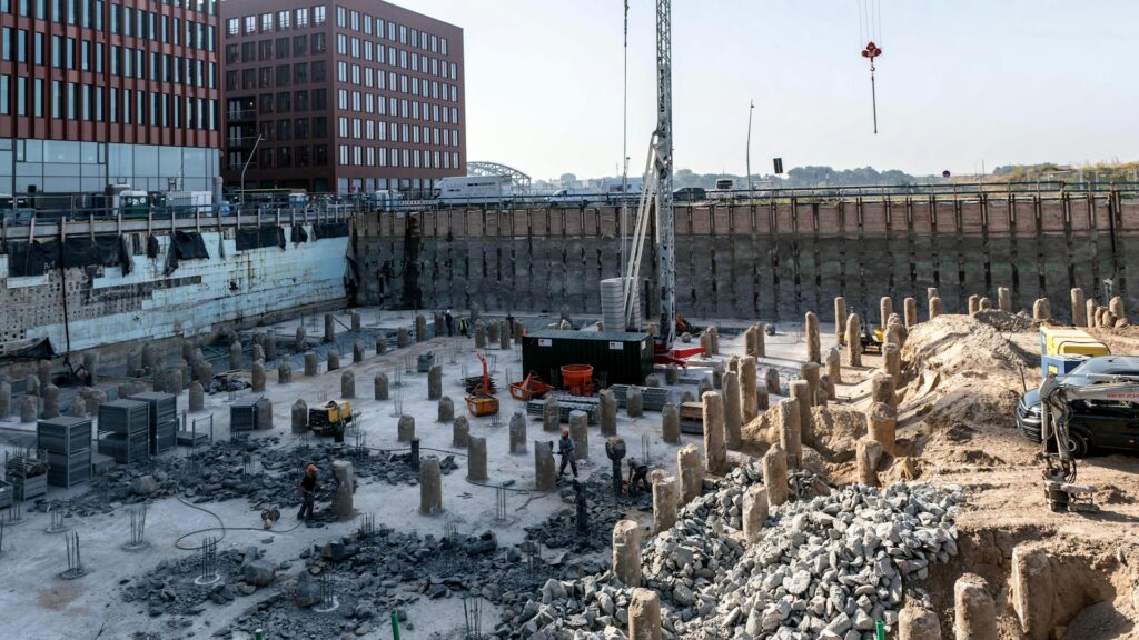
5.B.1 Pile Footings
Pile footings are slender, columnar elements—timber, precast concrete or steel—driven or drilled into deep soils to reach stable strata or mobilize skin friction along their length. End-bearing piles terminate on rock or dense soil layers, transmitting loads directly through the pile tip, while friction piles rely on shear resistance between the pile surface and surrounding soil over the embedded length. Pile groups are capped with a concrete pile cap, ensuring load distribution among multiple piles and resistance to bending and uplift.
5.B.2 Caissons (Drilled Shafts)
Drilled shafts or bored piles—also called caissons—are large-diameter cylinders cast in situ by excavating a hole, installing reinforcement, and pouring concrete, often through a tremie pipe in wet conditions. They offer high load-bearing capacity with minimal vibration, making them suitable for bridge piers, deep foundations under high-rise buildings and sites with sensitive adjacent structures. Unlike driven piles, caissons are sized and reinforced to resist lateral loads, bending moments and uplift forces, providing versatility in both end-bearing and friction capacity designs.
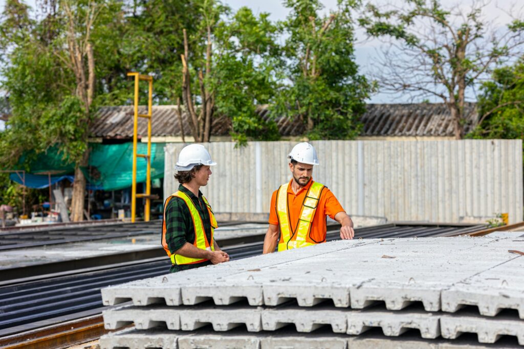
6. Precast Concrete Footings
Precast concrete footings are factory-manufactured structural elements delivered to site ready for installation, offering builders a predictable, high-quality solution that minimizes on-site risks and accelerates schedules. By casting footings under controlled conditions, precast producers achieve consistent mix strengths (often exceeding 5,000 psi), tight dimensional tolerances and integrated features (anchor slots, insulation pockets) that traditional cast-in-place methods struggle to match. This section explores the benefits of precast footings and where their unique strengths deliver the most value.
6.1 Why Precast Concrete Footings?
- Faster Construction Timelines 🚀 Precast footings from the factory eliminate on-site forming and curing delays—up to 50 % faster than cast-in-place concrete footing methods in footing construction.
- Better Quality Control in a Factory Consistent high-strength precast mixes (5,000–6,000 psi) and precise tolerances reduce rework in concrete footing detail and ensure performance.
- Stronger, More Durable Footings Low water-cement ratios in precast concrete footings yield dense, low-permeability concrete resistant to freeze–thaw cycles and chemical attack.
- Reduced On-Site Labor No formwork erection or mixing; labor hours drop by 30–40 % in precast footing construction.
- Lower Long-Term Maintenance Factory-sealed joints and controlled curing minimize cracks in precast concrete footings over time.
- Weather-Independent Manufacturing Climate-controlled precast plants avoid weather delays common in cast-in-place concrete footing construction.
- Material Waste Reduction Bulk mix optimization and water recycling in precast production cut waste by 20 % compared to field batching for concrete footings.
- Cost-Effective for Large Projects Precast footings benefit from economies of scale, reducing unit costs by 15 % on high-volume orders.
- Integrated Insulation & Embedments Cast-in anchors and insulation pockets in precast footings simplify installation and enhance performance in footing construction.
- Factory Strength Testing Routine cylinder breaks and non-destructive testing in precast plants provide real-time quality data for concrete footings.
6.2 Where Precast Footings Shine
Residential: Speed and Stability
From single-family homes to townhouse clusters, precast footings simplify tight-site logistics, providing immediate bearing capacity for floor systems and crawlspace foundations. For example, Superior Walls’ insulated panels have been used in cold-climate homes to expedite framing after footing placement.
Commercial and Industrial: Handling Heavy Loads
Warehouses, tilt-up concrete walls and light-industrial structures use precast pile caps and deep-beam footings to support crane loads and heavy material storage racks with minimal deflection.
Infrastructure: Bridges and Roads
Precast caisson shells and pile-cap units can be mass-produced for highway bridges, reducing lane-closure durations and minimizing traffic impacts during foundation installation.
Utility: Poles and Towers
Power-line poles, cell-tower foundations and light-pole bases benefit from precast footings that resist rot, decay and pests, ensuring decades of stable support with virtually no maintenance.
Specialized Applications
- Decks, Porches & Garages: EZ-Crete’s 750 lb precast footings provide instant support for post bases in residential additions, eliminating mixing delays and forms on tight-access sites.
- Pole Barns & Agricultural Buildings: JR Precast deck footings and Nitterhouse pole-barn footers save contractors time and money by pre-manufacturing pier bases to resist heavy loads and ground moisture.
- Basements & Crawlspaces: Precast wall panels with integrated footings create weathertight below-grade assemblies, speeding interior finishes and reducing waterproofing risks.

7. Common Mistakes and How to Avoid Them
Concrete footings are the foundation of any construction project, yet even experienced builders can make errors that compromise load-bearing capacity, introduce settlement risks or accelerate cracking. By recognizing the most frequent mistakes—from site preparation and excavation through mixing, placement and curing—contractors can implement targeted solutions to deliver footings that meet design intent and service demands. Below are the top pitfalls and how to overcome them.
Poor Site Preparation: Loose soil settles. Compact subgrade to 95 % Proctor density.
Wrong Excavation Depth: Shallow or narrow trenches under-size the footing. Verify with laser levels.
Incorrect Mix Design: Too much water reduces strength by up to 40 %. Specify ACI 211.1 mixes and use superplasticizers.
No Curing: Rapid drying causes shrinkage cracks. Keep footings moist for seven days.
Misplaced Rebar: Floating bars corrode and fail. Use chairs for correct cover and tie laps per design.
No Control Joints: Long strip footings crack randomly. Introduce relief notches or shrinkage steel every 20 ft.
Poor Formwork: Leaks and misalignment cause honeycombing. Seal joints and brace forms properly .
Ignoring Weather: Hot pours shrink; cold pours freeze. Cool aggregates or heat enclosures as needed .
Quantity Errors: Under-ordering causes cold joints; over-ordering wastes cubic yards. Calculate volume and add 10 % contingency.
No Inspections: Unchecked errors become failures. Schedule checks at excavation, rebar and post-pour stages.
8. Maintenance and Repair
Maintaining and repairing concrete footings is crucial to preserve load-bearing capacity, prevent settlement and avoid costly structural failures over a building’s life. Regular maintenance extends the life of footing assemblies by minimizing moisture intrusion, soil erosion and minor cracking before they become major defects. Regular inspections (biannual and post-storms) catch early issues—hairline cracks, efflorescence or soil washout near foundation walls and dirt floors .
Key steps include:
- Drainage & Grading: Slope grade 6 in over 10 ft from foundation and extend downspouts 5 ft away.
- Crack Sealing & Waterproofing: Use urethane sealants for cracks <1/8 in and apply waterproof membranes on exposed footing walls.
- Underpinning/Piering: Install push or helical piers to transfer loads to deep soils when settlement occurs.
- Slab Jacking & Foam Injection: Lift settled slabs with grout or high-density foam for minor settlements.
After repair, monitor with gauges or inclinometers for 6–12 months to confirm stability and document all maintenance activities.
9. Conclusion
Concrete footing design and construction underpin a stable foundation by converting a structure’s weight into safe soil bearing pressures, whether through isolated footings, continuous strips, raft slabs, or deep basement footings . Reinforcing with rebar addresses tensile forces, while attention to soil bearing capacity, frost depth, and code requirements ensures performance under diverse soil conditions.
Book your Demo with BuildTwin Success AdvisorFrequently Asked Questions (FAQ)
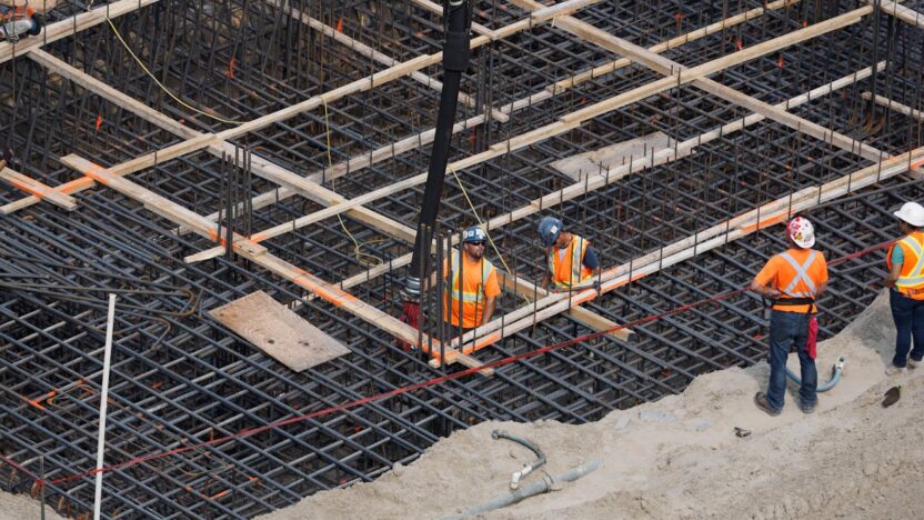
How are concrete footings constructed?
Concrete footings are typically constructed by excavating a trench to the required dimensions, placing rebar reinforcement, and pouring concrete into the trench. The size and placement depend on the soil conditions and the type of structure being built.
What are the advantages of using precast concrete footings?
Precast concrete footings offer several benefits, including:
– Superior quality control due to factory production
– Faster construction timelines with off-site manufacturing
– Reduced weather-related delays
– Consistent strength and durability
– Less on-site labor required
Footing construction typically involves excavating trenches to the required depth and width, placing rebar reinforcement, and pouring concrete into the trench. The dimensions and placement of footings depend on soil conditions, building load, and local building codes
What should be considered when selecting concrete footing types for a project?
Key considerations include soil bearing capacity, building load, local climate, and construction timeline. The right concrete footing type ensures long-term performance and minimizes settlement or structural issues
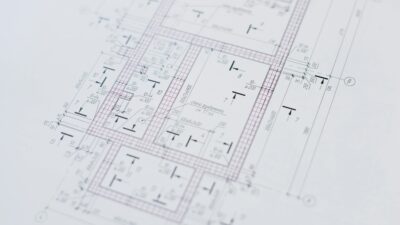
How do engineers determine the right concrete footing detail for a project?
Engineers assess soil conditions, building loads, and environmental factors to design the appropriate concrete footing detail. This includes specifying the size, depth, reinforcement, and type of footing to ensure structural stability and compliance with codes